Wheatstone bridge, metre bridge and potentiometer
The balanced Wheatstone bridge, the metre bridge and its end errors, measuring resistivity, and the potentiometer for comparing emfs, measuring internal resistance and small p.d.s.
The Wheatstone bridge
Four resistors $P$, $Q$, $R$, $S$ form a diamond. A cell is connected across one diagonal and a galvanometer across the other. The bridge is balanced, with no current through the galvanometer, when $$\frac{P}{Q} = \frac{R}{S}$$ At balance the two ends of the galvanometer are at the same potential. The condition does not depend on the cell's emf or the galvanometer's resistance. A sensitive galvanometer only makes it easier to find the balance point.
The metre bridge
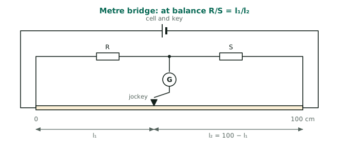
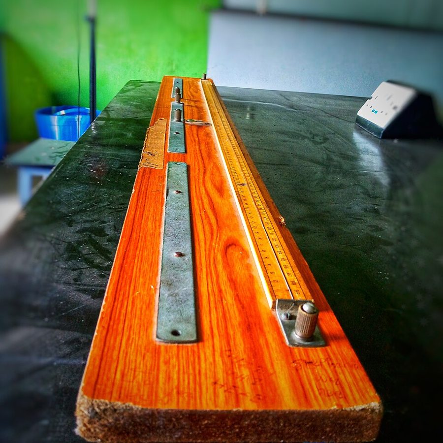
A uniform resistance wire $100\ \text{cm}$ long replaces two arms of the bridge. Its resistance is proportional to length. With a known $R$ in one gap and the unknown $S$ in the other, slide the jockey to the balance point at $l_1$: $$\frac{R}{S} = \frac{l_1}{100 - l_1}$$
- Choose $R$ so that the balance point is near the middle of the wire. The percentage error in measuring $l_1$ and $l_2$ is then smallest.
- End errors: the thick copper strips and contact points add small unknown resistances at the ends. Swap $R$ and $S$, balance again and average the two results. This cancels them.
- Press the jockey lightly and briefly. Scraping the wire changes its uniformity, and a steady current heats it.
Resistivity: find the resistance $S$ of a measured length $L$ of wire. Measure its diameter $d$ with a micrometer at several places and directions, and take the mean. Then $$\rho = \frac{S\pi d^2}{4L}$$ Resistivity must always be given with the temperature at which it was measured. (2023 Paper II, Q4.)
The potentiometer
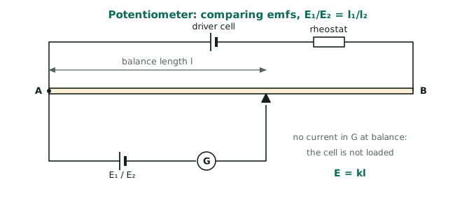
A driver cell sends a steady current through a long uniform wire AB. The p.d. along the wire rises in proportion to length: $V = kl$, where $k$ is the potential gradient ($\text{V m}^{-1}$). A cell or p.d. to be measured is connected from A through a galvanometer to a jockey. At the balance length $l$, no current flows in the galvanometer, so $$E = kl$$ Because the test cell supplies no current at balance, there is no $Ir$ drop. The potentiometer measures the true emf, unlike any voltmeter.
- Comparing emfs: $\dfrac{E_1}{E_2} = \dfrac{l_1}{l_2}$.
- Internal resistance: balance the cell on open circuit ($l_0$), then with a resistor $R$ across it ($l$). Then $\dfrac{E}{V} = \dfrac{l_0}{l} = \dfrac{R + r}{R}$, so $r = R\dfrac{l_0 - l}{l}$.
- Small p.d.s (thermocouple emfs): put a large series resistance with the wire so that the potential gradient is tiny (say $1\ \text{mV m}^{-1}$).
Conditions for a balance point to exist: the driver cell's emf must be greater than the p.d. being measured, and like terminals (both $+$) must be joined at A.
Example: A $100\ \text{cm}$ potentiometer wire of resistance $10\ \Omega$ is in series with a resistor $R$ and a $2\ \text{V}$ cell of negligible internal resistance. A $10\ \text{mV}$ source balances at $40\ \text{cm}$. The gradient is $\dfrac{10\ \text{mV}}{40\ \text{cm}} = 0.25\ \text{mV cm}^{-1}$, so the whole wire has $25\ \text{mV}$ and the current is $\dfrac{0.025}{10} = 2.5\ \text{mA}$. Then $R = \dfrac{2 - 0.025}{0.0025} = 790\ \Omega$. (A 2024 Paper I question.)
Photo credits: Meter bridge 001.jpg by Jeremyida002, CC BY-SA 4.0.
